
One of the most challenging aspects of the architectural design process is determining how to organize form to fit an overall parti. Facing endless possible geometric configurations, making sequential alterations towards a fitting result can be difficult without a means to measure suitability. During the initial phases of design research, an architect gathers essential information such as program requirements to meet a clients needs, zoning and code information for a provided site, environmental and material influences, and aesthetic preferences. These assets serve as the foundation for a constraints based design approach where parameters can be assigned in an effort to influence and control form.
Constraints in design are rules or vocabularies that influence form through the design process. An inherent feature of the architectural process is that design must be performed within a set of given parameters. Parameters help to focus the scope of an architect by narrowing the range forms and formal relationships may take within a design solution... Constraint based design takes the parameters associated with a design problem and links them to the attributes of the formal components and relationships of a solution.
(Dustin Eggink,
http://goo.gl/EktbQ1
)
Dynamo is an ideal platform for constraints based design because the visual programming environment allows you build a parametric model that can be quickly adjusted with changes to input values.

Once you have a functioning Dynamo definition, all of the nodes can be consolidated into one Custom Node by dragging a selection window over everything and going to Edit > Create Node From Selection. This will transition everything to the custom node editing mode -- you can always tell when you are in this mode because the background is yellow.

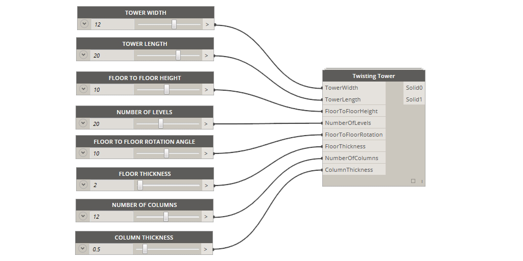
To create a custom node, the first step is to give it a name, description of what it does, and category (where it will be saved in the Library). All of the input number blocks (far left side) must be swapped out for Input nodes, generally named for the variable they represent. Output nodes also need to be added after the final nodes in the definition (far right side) that are providing the finalized geometry. When these steps are complete, save the node. Back in the Dynamo node space -- also known as the canvas -- number sliders can be added to the newly-created custom node. It is helpful to click the down arrow on the left side of the node to set the minimum, maximum, and step interval because large numbers can take awhile to process or crash Dynamo while zeros will often create null values and turn the majority of your definition yellow with warnings. Now you have a fully parametric custom node that allows you to explore a range of formal configurations with the simple adjustment of number sliders.
Developing custom nodes for form making allows for use with the Dynamo Customizer -- a web-based viewer currently in beta for viewing and interacting with Dynamo models real-time. This platform has a lot of potential for sharing designs in the future and allowing colleagues or clients to experiment with their own manipulations of the design.

Check out this example for the twisting tower here:
Dynamo Customizer - Twisting Tower.
DISCLAIMER: you will have to request Beta access and sign in with your Autodesk ID to view this. For step-by-step instructions, visit:
http://dynamobim.org/dynamo-customizer-beta-now-available/.
After guiding parameters have been established, a design space can be generated for testing all possible variations of a few select variables of a design. Design space exploration is a concept involving a virtual -- or non physical -- space of possible design outcomes. This allows the designer to simultaneously see a wide range of options and extract only those that satisfy pre-determined criteria of fitness.
The core essence of this workflow is the use of Cartesian product which facilitates comparison of all possible pairings of variables. This mathematic operation can be understood as an array of combinations between x, y, z and 1, 2, 3 (below left) or as a slope graph of all possible correlations between the two lists of variables (below right).

Using the List.CartesianProduct node calculates all possible combinations of the number range values however all of the geometry is instantiated in Dynamo at the origin point, making it appear that only one object was created even though the count shows 132 (below left). Thanks to Zach Kron and the Design Options Layout node from the Buildz package, the nested list clusters of geometric objects are arrayed according to the Grid Size spacing value (below right). Using list management logic -- such as List.Transpose, List.Map with List.Transpose, etc. -- before the Design Options Layout node will re-arrange the list structure and result in different compositions of objects.

To set up a design space in Dynamo, the inputs to the custom node are fixed values. Whichever variables that you want to test must be left empty on the custom node and number ranges are connected to the List.CartesianProduct node. The number of list inputs in List.CartesianProduct must match the number of inputs left open on the custom node. It is also important to note that the list order for the number ranges in the List.CartesianProduct node must correspond to the same order of inputs in the custom node. The total number of values from each number range will not only determine the scale and form of the resultant geometry but count of values in each list will determine the overall size and shape of arrayed objects -- this is critical to remember because an excessive number of input values may take several minutes to process or potentially crash Dynamo. After the ranges of values have been set up, the List.CartesianProduct node is connected to the Design Options Layout node which arrays all possible combinations in 3D space. Depending on the geometry being tested, the Grid Size input determines the spacing between objects. When everything is connected correctly, Dynamo will display an array of forms which can be altered by changing the number range inputs and re-running the definition. If Dynamo crashes, geometry disappears, or there is an insufficient amount of variation in the forms, continue to calibrate the number ranges and explore the limitations of the parameters in your custom node.

A successful design space arrays all possible options along two or more axis utilizing the concept of dimensionality. Design space is theoretically unlimited, however the visualization of the virtual design space is limited to the constraints of graphic representation. Color can be added to provide visual differentiation of a third dimensions such as the analysis of generated outcomes, or could represent any of the associated properties of variables. Criteria for evaluation of fitness refers to the means by which the best solution is determined.
For example, a calculation of height of twisting tower forms can be colorized on minimum to maximum gradient (below left). Another representational technique is selective omission or hierarchical modifications to the representation (below right).

Ultimately design space and its subsequent representation is nothing more than a tool, designers still have to make decisions. Design space should function as a method of exploration to make informed, confident, substaintiated decisions.
Portions of this blog post were developed in collaboration with
Jamie Farrell
for our course Advanced Revit and Computational Workflows taught at the Boston Architectural College.