Image courtesy of Hung Pham
Canstruction is an international competition where “cansculptures” are created using cans of food, which are later donated to local hunger relief organizations. This year, the Houston office of Shepley Bulfinch assembled a team to take on the challenge.
After coming up with a design concept, the task of estimating the number of cans and positioning for structural stability is daunting. Since cans of food are a modular unit with standardized dimensions, this is a perfect opportunity for parametric design using Dynamo.
PREPARATION
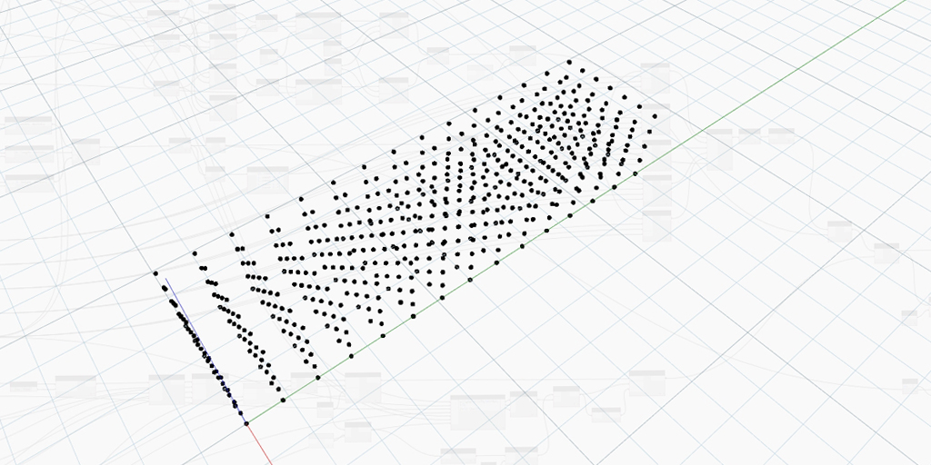
The first step was to figure out how to populate cans along a surface. Following a visit to a local grocery store for research, the height and diameter of a chosen can were entered into Dynamo to establish the base module. An undulating vertical cylinder was created to a height of 6 Feet and cross-sectional circumference curves were cut based the height of the can.

Points were then placed along the horizontal curves at a repeated distance of the width of the can. In order to ensure structural stability, the last step was to offset the location of the points along every other curve by the distance of half a can width so that they would be perfectly staggered to land at the point of intersection of two cans on the level below.

DESIGN
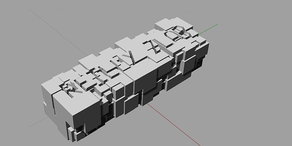
For the final design concept, the character Blanky from the animated classic The Brave Little Toaster was chose to help convey the message “Stitching Away Hunger!”

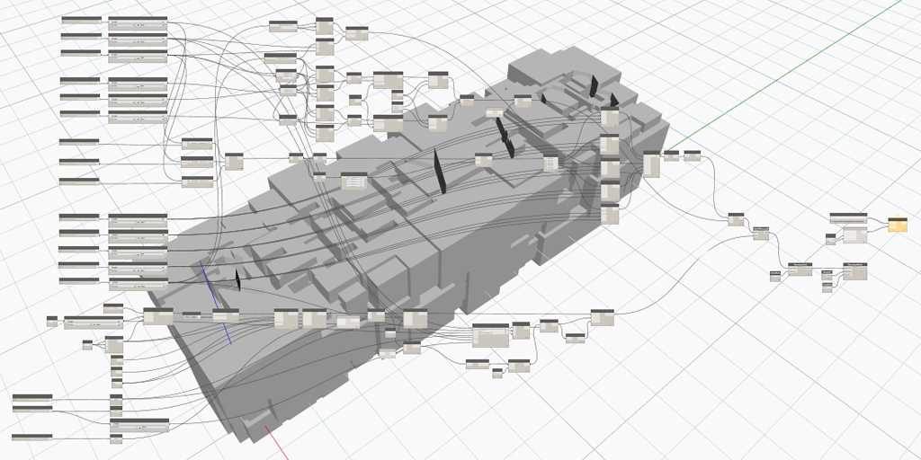
The initial 3D object to visualize the Blanky’s body was created using NURBS in Rhinoceros and then imported into Dynamo using the Mantis Shrimp package from Archi-lab . Initial attempts at generating curves from the Rhino surface resulted in a significant loss of definition of features due to the NURBS curves in Dynamo rounding off sharp corners between points.
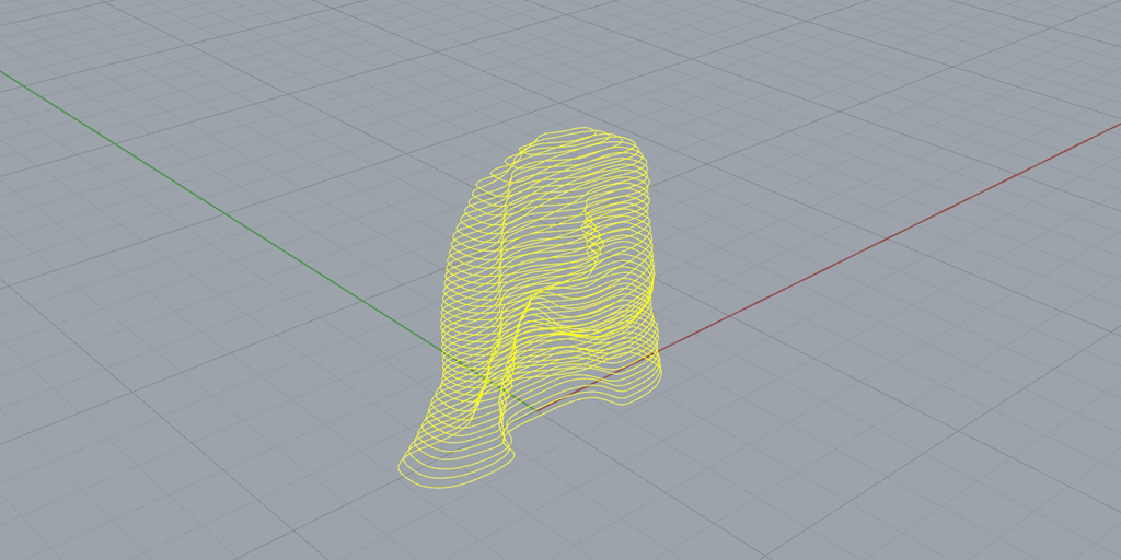
MODIFICATION
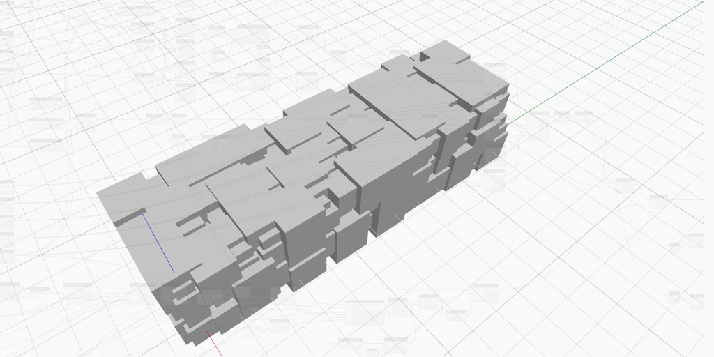
It was determined that a better approach would be to model the concentric curves, similar to a digital topography model. The geometry was transitioned to Revit where contour lines were generated at a vertical spacing of the height the can. As splines in Revit, the contour lines could be easily adjusted to maintain the precision of the shape’s features.

Dynamo facilitated a seamless iterative design process as the contour curves were adjusted in Revit then queried in the definition to populate with cans. Upon visual inspection of the resulting 3D geometry in Dynamo, further adjustments could be made to the curves in Revit to perfect the overall shape.

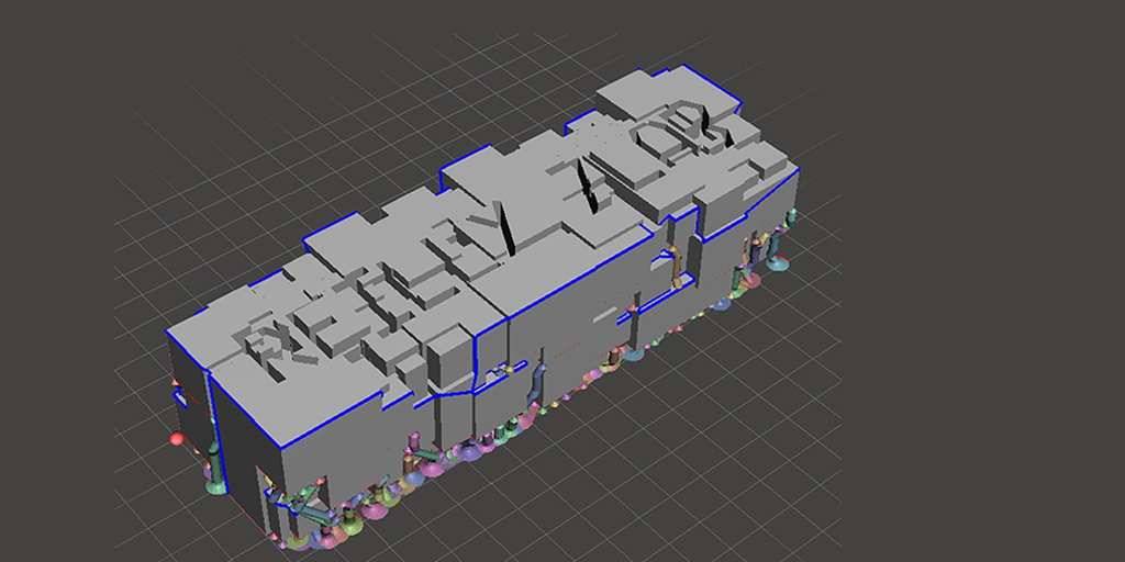
REINFORCEMENT
Cans tend to become unstable after a certain number of stacked layers so a common practice is to add a thin layer of supporting material at regular intervals to provide a firm horizontal surface. The team chose 1/16” medium-density fiberboard (MDF) as their horizontal reinforcement layer at every level of cans and added supplemental contour curves in Revit to simulate the 1/16” spacing. The curves were picked up in Dynamo and populated with an extruded surface to and visualize the addition of supports, as well as calculate the increased overall height.
To emphasize the distinction between the character’s cape and the void below, the decision was made to use taller cans of a different color for the lower central portion of the can sculpture. In order to account for this design alteration, the contour curves were strategically split in Rhino and – at areas to be substituted with larger cans – contour lines were removed to account for the increased height.

TAKEOFFS
One of the most significant benefits of designing a Canstruction sculpture with computation is the ability to perform an instantaneous takeoff of cans and materials. For this cansculpture, the final count came to 1763 short cans and 120 regular cans. In addition, there were 42 layers of support material, which ended up requiring [60] sheets of MDF. These numbers were critical for designing within budget and placing supply orders.

Image courtesy of Billi Jo Galow
TEMPLATES
Linework from Dynamo can be pushed back into Rhino or exported as an SVG file. In preparation for build day, the assembly team printed out full-scale templates at each level of the cansculpture, which allowed them to quickly place cans on top of the template, eliminating most unforseen variances and the need for improvisation in the field.

Image courtesy of Billi Jo Galow
TEAM
Congratulations to the Shepley Bulfinch – Houston team for constructing an impressive cansculpture for a good cause. It was a pleasure to assist with the use of Dynamo and interoperability among several software platforms for simulation and delivery of their design. They demonstrated that visual programming is easy-to-learn and invaluable tool for integration into the design and documentation process, whether producing a sculpture made of cans or an entire building.
Claudia Ponce
Hung Pham
Julie Truong
Billi Jo Galow
Sandra Bauder
Stan Malinoski